Trouble Shooting
GTS offers emergency service, Preventive Maintenance contracts, telephone support and an extensive inventory of new and refurbished parts. For contact information click here.
- I am getting set up errors, what do I do to correct this?
- How do I determine blade exposure?
- Spindle Removal for DAD 2H/6 and DAD 2H/6T
- Spindle Removal for Disco 320, 321, 350, 351, 360, 361
- Spindle Removal for Disco 340, 341, 381, 641, 651
- Spindle Removal for K&S 780 & 980
- Spindle Removal for ADT 7100 2"
- Spindle Removal for ADT 7100 4"
- The Identification of and DIP Switch Settings for the Disco Motor Control Card FBPCB-0076 and FBPCB-0381
- Disco 300/600 Series Saw Will Not Boot/Initialize Properly
- Procedure for Installing and Re-teaching the Height Button on a K&S 780 or 980 Dicing Saw
- K&S 780-980 Saws Chuck Open Error
- Information about the GTS Utilities Block
- Checking Run Out on a Wheel Mount or Flange
- How to Manually Dress a Flange
- How to Manually Dress a Wheel Mount
I am getting set up errors, what do I do to correct this?
The set up circuits on Disco and K&S saws are similar in that they apply a voltage to the chuck table and ground the spindle so that when they touch the voltage is detected by the machine. If the chuck is grounded or the spindle brushes are open, the machine cannot work properly.
To check to see if the chuck is grounded abnormally, turn the machine off and follow the instructions relative to your machine type:
Disco 300 and 600 Series
The chuck table is normally grounded; the machine only removes ground during a set up. With the machine off and the bellows off, use a Multi-meter in the resistance setting and check to see if the chuck is grounded (it should be). For test points, use the top of the chuck and the spindle nose (Make sure you have the air on to the spindle). Any place on the frame will be grounded, as long as it is below the white ceramic insulation plate. If it is NOT grounded, then there is a disconnected wire between the chuck and EMSURAM board. Look for it starting at the top chuck table and trace the wires back to the card cage. Repair or replace the broken wire(s). Please call GTS and let us know what you need.
Assuming that the chuck is grounded properly in the first step, turn off the power and open the card cage. Find the 8 position connector labeled "SUIN" located on the EMSURAM board. Disconnect it and then using the same procedure from step one, check to see if the chuck is grounded. It should not be grounded. If it IS grounded, the most likely cause is water.
If there is any evidence of water (water, rust, residue, etc.) then clean the Theta and X-axis off with paper towels, use compressed air to blow of all of the nooks and crannies of the area. Be sure to remove any rust or residue as well as this can be conductive. You can also (and might have to) wait over night for things to dry out on they're own. You will also need to try and determine where the water is coming from, and repair or replace the parts needed. Please contact GTS and let us know what you need.
If everything checks out good and you are still getting errors, you will need to check the spindle carbon brushes. With the machine off and the air flowing to the spindle use a multi-meter on the resistance setting to check the brushes on the back of the spindle. There are the 2 metal tabs held by screws in the center of the spindle. Place your test leads on each of the screws they should be shorted together with no more resistance than about 10 ohms. Carefully rotate the spindle nose with your fingers to see if the resistance changes a lot. If you see the resistance is open, changes (by more that 20 ohms), or jumps then you will need to replace the brushes. Also be sure to check the wires that come from the brushes, make sure they are not damaged or broken. Call GTS for further assistance and parts.
NCS Setups:
If your machine is equipped with a Non Contact Setup option, follow this procedure to check it out. The first thing to do is refer to your Maintenance Manual; there is a section that refers to cleaning and adjusting the NCS prism and amp. Follow these procedures and if you still are having issues, check to make sure the prism is not damaged as well as the fiber cables and wiring. Repair or replace parts as necessary. Please call GTS if you need further assistance.
Disco 2H/6 Series
Refer to the instructions in the 300/600 series section as it is pretty much the same concept. The biggest different being the set up board is next to the X-axis on the right hand side of the saw. It is the "touch sensor board" and you will need to unplug the 5 position connector, it's the smaller of the 2. So, with the machine off, test to see if the chuck is grounded, it should be otherwise look for a broken wire. Then unplug the connector and check for ground again, it should not be grounded, if it is, look for water leaks or another path to ground. Then check the spindle brushes and wires. Call GTS for further assistance and parts.
K&S 780 and 980
For the K&S saws, the easiest way to check for proper ground is to first turn off the machine, leave the air on. Use a multi-meter on the resistance setting to check ground between the chuck and spindle nose. It should be a near short. If it is NOT grounded, check for broken wires from the theta to the card cage and from the spindle brushes to the card cage. Repair or replace as needed, call GTS for further assistance.
Next remove the Main Logic Card from the machine and check the same test points from above to see if the chuck is grounded. It should NOT be. If it is, look for water leaks or damaged wires and repair or replace parts as needed. Call GTS for further help.
If there is any evidence of water (water, rust, residue, etc.) then clean the Theta and X-axis off with paper towels, use compressed air to blow of all of the nooks and crannies of the area. Be sure to remove any rust or residue as well as this can be conductive. You can also (and might have to) wait over night for things to dry out on they're own. You will also need to try and determine where the water is coming from, and repair or replace the parts needed. Please contact GTS and let us know what you need.
If everything checks out good and you are still getting errors, you will need to check the spindle carbon brushes. With the machine off and the air flowing to the spindle use a multi-meter on the resistance setting to check the brushes on the back of the spindle. There are the 2 metal screws in the center of the spindle. Place your test leads on each of the screws they should be shorted together with no more resistance than about 10 ohms. Carefully rotate the spindle nose with your fingers to see if the resistance changes a lot. If you see the resistance is open, changes (by more than 20 ohms), or jumps then you will need to replace the brushes. Also be sure to check the wires that come from the brushes, make sure they are not damaged or broken. Call GTS for further assistance and parts.
For off chuck setups:
If your machine is equipped with an off chuck height button, check to see if there is continuity between the button and the chuck, if there is not, check the wiring between the button and the theta electrical box. Repair it or replace as need, let GTS know if you need parts. You may also need to replace or readjust the height button. If you are not familiar with this procedure, please call GTS and we can help you with this.
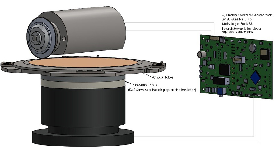
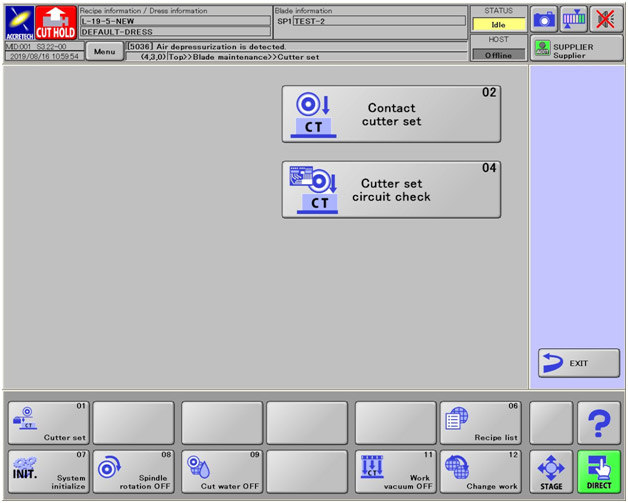
Accretech SS Circuit Check
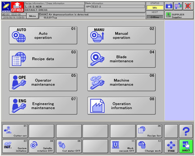
With this guide below you will be able to do the cutter set Circuit Check for the Accretech SS machine.
Main Screen:
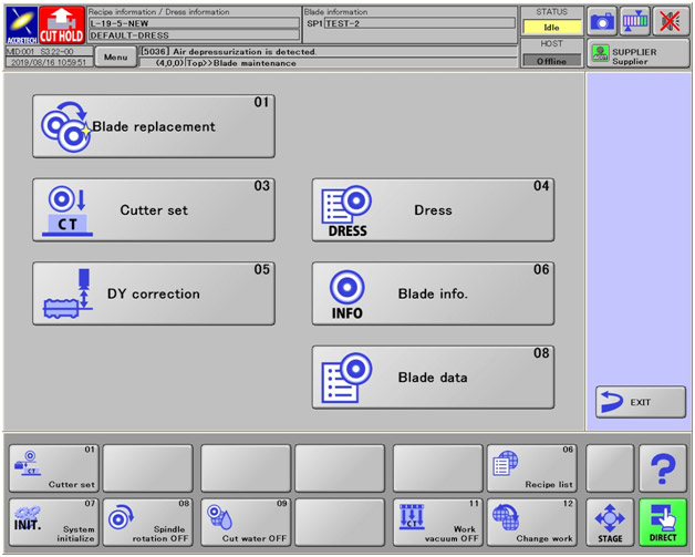
Blade maintenance (Cutter Set):
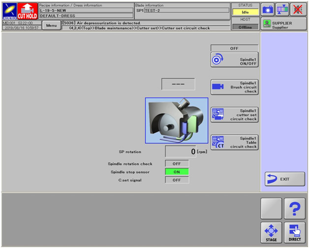
Cutter Set Circuit Check:
Then from here you will be able to check:
- Spindle
- Spindle brush circuit check
- Spindle cutter set circuit check
- Spindle table circuit check
How do I determine blade exposure?
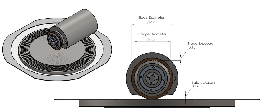
Besides which type of blade to use for your application, choosing a blade with the correct exposure is probably the most important consideration during selection. The exposure must be long enough to:
A) Cut through the material you are dicing
B) Cut partially into your mounting substrate
C) Accommodate the safety margin that you have programmed into your saw
Things to bear in mind are that you want enough exposure to accommodate these three points, but you also want to keep it as small as possible to avoid poor cut quality. If a user slaps a thin blade onto a saw and commences to cut a relatively thick material, chances are extremely good that they will end up with a wavy cut, or worse, broken blades. There is a universal ratio (again…not always applicable) that we use to figure our exposure in relation to the thickness. The ratio is 30:1. Basically, if your blade is .001" thick, the longest exposure you want to use would be .030". Conversely to that…if you choose a blade that does not have a long enough exposure, you can run the risk of crashing the flange into the top of the material that you are dicing. This is where the safety margin comes into play. Most saws will have a screen in their menus that will allow you to set a value at which point the saw will error out as the blade wears. This value lets the saw know how close the flange can come to the top of the part before it forces you to change the blade.
But how do I determine how deep I want to cut into my mounting film? Good question! The universal rule is that however wide your blade is, you want to cut at least half that deep into the tape. So…if you have that same .001" thick blade, you will want to be cutting at least .0005" into your mounting tape. Believe it or not, this actually DOES serve a purpose. Refer to Figure 2.
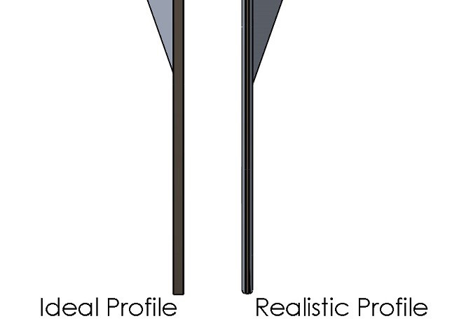
In an ideal world, the profile of your blade will stay sharp and square during the dicing process. Unfortunately, the corners on the edge of the blade tend to wear faster than the bottom causing what we call the "Bull-Nose" profile. If this bull-nose profile is not well below the bottom-side of your wafer, the increased cutting forces of this profile can cause bottom-side chipping.
Spindle Removal for DAD 2H/6 and DAD 2H/6T
Removal of the Spindle
- Move Y axis all the way to the front.
- Move X axis all the way to the Right.
- Power down machine and cut the power to the machine.
- Turn off all water coming into the machine.
- Turn off all air to the machine.
- Remove Wheel Cover ,Wheel Mount and Blade Water Nozzle from the spindle
- Take off the Splash Plate, Guide Plate, and Seal from around the spindle
- Remove all air and water tubing going to the spindle and if equipped from the Spindle Cover.
- Make sure to label the water/air tubing so you will know were they go when you reinstall the spindle.
- Note: on the 2/H6 you will need to remove the black plastic Spindle Cover.
- Unplug the Nylon Connector from spindle inverter (Note: this connector can be a blue Nylon or round Steel Connector.)
- Make sure to take wires off from Carbon Brushes but keep the brushes in the spindle.
- Before loosening the bolts on the Rocker Case, make sure that you measure the distance from the back of the spindle motor to the Rocker Case. You will need this value for when you reinstall the spindle.
- Take out the two Soc HD screws out of the Rocker Case.
- With a screw driver carefully wedge it into the Rocker Case were the screws were in step 13 and pull the spindle towards the back of the machine. (You DO NOT have to pry open very much to remove spindle).
(Bold words are from the Disco Parts Description in the exploded view page)
Putting Spindle Back In
- Reverse all steps from "removal of spindle" to reinstall the spindle.
- Once the Spindle has been reinstalled and power, air and water is hooked up. You will need to make sure the spindles 90 degree right angle and spindle pitch is with in OEM Spec. If the spindle is not in the correct angle, blade breakage, chipping, poor cut quality and trapezoidal parts maybe a result.
- Tools needed to perform above tasks.
- Mounting Plate
- Right angle square
- Small magnetic stand with a 1um dial indicator
- Spindle right angle jig
* If you do not have the tools needed to perform the above tasks, give GTS a call to set up a service call with one of our Service Technicians to come out to realign the spindle for you.
Spindle Removal for Disco 320, 321, 350, 351, 360, 361
Removal of the Spindle
- Turn off all power and water to the Machine.
- Measure the distance from the back of the spindle to the edge of the spindle housing. Record the measurement for reinstallation.
- Move X axis all the way to the right.
- Remove Ring(Splash), Plate(Splash), Plate(Guide), and Rubber (Splash)
- Remove Blade cover, Blade water nasal and Hub flange from the front of spindle
- Remove all water and air hoses from the back of the spindle. (Make sure to mark them.)
- Remove wires from the Carbon brushes on the back of the spindle. Make sure to screw back in Carbon brushes.
- Unplug Power Connector (Round) from the power inverter.(Some may have 4 wire Nylon connector also)
- Make sure to mark Nylon connector and remove the 4 wires.
- Unplug the Thermistor Unit from the top of the Z axis unit (Just above the spindle).
- Loosen Hex bolts on the left side of the Spindle casting. When loose, slowly tighten down the bolts around the hex bolts just enough to be able to move spindle backwards
Putting Spindle Back In
- Reverse all steps from removal of spindle
- You will need to put the spindle back in the housing using the number that you recorded from step 2 of spindle removal.
- Once Spindle is back in and everything is back together. You will need make sure the spindles 90 degree right angle and spindle pitch is with in OEM Spec
- Tools need to perform above tasks.
- Mounting Plate
- Right angle square
- Small magnetic stand with a dial indicator
- Spindle right angle jig
* If you do not have the tools needed to perform the above tasks - Give GTS a call to set up a service call for one of our Service Technicians to come out to realign the spindle for you.
Spindle Removal for Disco 340, 341, 381, 641, 651
Removal of the Spindle
- Move X axis all the way to the right.
- Turn off all power, air and water to the Machine.
- Remove Blade Cover, Blade Water Nozzle and Flange from the spindle
- Remove Ring(Splash), Plate(Splash), Plate(Guide), and Rubber ( Splash)
- Remove all water and air tubing going to the spindle.
- Be sure to label the water/air tubing so you will know where they go when you reinstall the spindle
- Remove wires from the Carbon Brushes on the back of the spindle. Make sure to screw the Carbon Brushes back in place.
- Unplug Power Connector (Round) from the power inverter.
- Unplug the Hall Sensor cable if equipped
- Next is the removal of the spindle from the casting. It is recommended that a second person be present to support the spindle while the four M6 socket head screws are removed from the flange of the spindle.
- For 681, 691, and 340's & 341's with 2.2Kw spindles, the process is the same, but there are four M8 socket head screws on the side face of the spindle instead of four M6 socket head screws on the front face.
- Once the spindle is free from the casting, move it forward to pull the cables through. The spindle may then need to be angled backwards to remove it from the machine.
(Bold words are from the Disco Parts Description in the exploded view page.)
Putting Spindle Back In
- Reverse all steps from removal of spindle
- Once Spindle has been reinstalled and power, sensor cable, air and water is hooked up, you will need to make sure the spindle's 90 degree right angle and pitch are within OEM Spec. If the spindle is not in correct angle, blade breakage, chipping, poor cut quality, and trapezoidal parts may be a result.
- Tools needed to perform above tasks.
- Mounting Plate
- Right angle square
- Small magnetic stand with a dial indicator
- Spindle right angle jig
* If you do not have the tools needed to perform the above tasks, give GTS a call to set up a service call with one of our Service Technicians to come out to realign the spindle for you.
Spindle Removal for K&S 780 & 980
Removal of the Spindle
- Turn off all power, water and air to the machine.
- Remove Wheel cover and Blade Water Nozzle along with all tubing going to the wheel cover.
- Remove all air/water tubing going to the spindle.
- Note: make sure to label the water/air tubing so you will know were they go when you reinstall the spindle
- Make sure to take wires off from Carbon Brushes but keep the brushes in the spindle.
- Remove the Nylon Connector from Power Inverter.
- Remove the 4 wires from the Nylon connector (Make sure to label Nylon connector so you will know what wire goes back in the right slot.)
- Remove the cover on the back right side of the machine.
- Pull power cable up through the machine until it comes out the back.
- Make sure that you measure the depth of the spindle. You will need this value for when you reinstall the spindle.
- Remove the two Hex Bolts from the left side of the Clam Shell ( Be careful there is a spacer in between the Clam Shell.
- Take one of the Hex Bolts and Spacer and screw it into the middle hole with a spacer between it and the Clam Shell. Tighten the Hex Bolt just enough to get the spindle loose. If you over tighten the Hex Bolt the Clam Shell will break.
- Pull the spindle out of the Clam Shell.
(Bold words are from K&S Description in the exploded view page.)
Putting Spindle Back In
- Reverse all steps from removal of spindle
- Once Spindle has been reinstalled and power, sensor cable, air and water is hooked up, you will need to make sure the spindle's 90 degree right angle and spindle pitch are within OEM Spec. If the spindle is not in correct angle, blade breakage, chipping, poor cut quality and trapezoidal parts may be a result.
- Tools needed to perform above tasks.
- Mounting Plate
- Right angle square
- Small magnetic stand with a dial indicator
- Spindle right angle jig
* If you do not have the tools needed to perform the above tasks. Give GTS a call to set up a service call with one of our Service Technicians to come out to realign the spindle for you.
ADT 7100 2" Spindle Removal and Spindle Install
Removal of the Spindle
- Disconnect the Blade and Wheel Mount.
- Move the X and Y Axes to their Home (zeroed) positions, as Follows:
- Click in the toolbar to display the Setup & Diagnostics workbook
- From the Setup & Diagnostics tree, select saw>Dicer>Stations>Home.
- In the upper right pane, click the row for the X Axis.
- Click Move. The X Axis moves to the Home position.
- In the upper right pane, click the row for the Y Axis.
- Click Move. The Y Axis moves to the Home position.
- Power down the system.
- Turn off the Water and Air Supplies.
- Remove the Rear Side Upper Left Panel.
- Open the Cable Carrier Bars.
- Disconnect all Plugs and Air and Water Tubes from the rear of the Spindle.
- Disconnect the three transparent Water tubes from the Cooling block.
- Remove the Broken Blade Detector (if there is One installed) from the Cooling Block and set it to the side or in a safe place.
- Remove the two screws securing the Cooling Block to the Spindle and remove the Cooling Block.
- Release the Spindle from the Spindle Bracket by removing the five screws from the spindle Flange, and carefully remove the Spindle.
Caution: Have some thing placed under spindle or someone holding the spindle from underneath before performing Step 11 to prevent the Spindle, from falling and damaging the system when released.
Putting Spindle Back In
- Position the new 2" Spindle in the system and secure it to the Spindle Bracket by replacing the five screws in the Spindle Flange
- Secure the Wheel Mount to the Spindle Shaft by rotating the Knob of the Removing tool clockwise.
- Rotate the Knob on the removing tool counterclockwise to release it from the wheel mount.
- Replace the wheel mount nut by turning the wheel mount spanner tool clockwise while holding the torque wrench
- Remove the wheel mount spanner tool from the torque wrench
- Attach the cooling Block to the spindle using the two securing screws.
- Reconnect the three transparent water tubes to the cooling block
- Manually move the Y axis to the rear of the system (Home position).
- Reconnect the plugs and Air and water tubes to the rear of the spindle.
- Close the cable carrier bars.
- Check all tube connections.
- Replace the rear side upper left panel.
- Turn on the air and water supplies to the system. Verify that there are no leaks in the tube connections.
- Power up system.
Once Spindle has been reinstalled and power, air and water is hooked up, you will need to make sure the spindle's 90 degree right angle and spindle pitch are within OEM Spec. If the spindle is not in correct angle, blade breakage, chipping, poor cut quality and trapezoidal parts may be a result.
Tools needed to perform above tasks.
- Mounting Plate
- Right angle square
- Small magnetic stand with a dial indicator
- Spindle right angle jig
* If you do not have the tools needed to perform the above tasks. Give GTS a call to set up a service call with one of our Service Technicians to come out to realign the spindle for you.
ADT 7100 4" Spindle Removal and Spindle Install
Removal of the Spindle
- Open the hinged portion of the Cooling block and remove the blade using the blade holder.
- Move the X and Y axes to their home (zeroed) positions as follows:
- Click in the toolbar to display the Setup & Diagnostics
- From the setup & diagnostics tree, select saw>Dicer>Stations>Home.
- In the upper right pane, click the row for the X axis
- Click Move The X axis moves to the home position.
- In the upper right pane, click the row for the Y axis
- Click Move. The Y axis moves to the Home position.
- Power down the system.
- Turn off the air and Water supplies to the system.
- Remove the rear side upper left panel.
- Open the cable carrier bars.
- Disconnect all plugs and air and water tubes from the rear of the spindle.
- Remove the maintenance panel on the left side of the spindle cover.
- Remove the eight screws securing the Z casting cover to the Z casting.
- Manually move the Y axis all the way to the front of the system.
- Cut the plastic ties securing the Vision system cables to the spindle.
- Disconnect the cable on top of the camera.
- Disconnect the Illumination cables from the microscope (the cabling may vary according to the illumination type used)
- Disconnect the cleaning air tube from the microscope.
- Disconnect the transparent water tubes from the cooling block.
Caution: The 4" spindle is heavy! Have someone hold or put something under the spindle before performing the next step to prevent the spindle, when released, from falling down and damaging the system.
- Cover the chuck to protect it from possible mechanical contact.
- Remove the four screws securing the cooling block to the spindle.
- Remove the cooling block from the spindle.
- Remove the chain front mount bracket holding the cables and tubes from the spindle housing.
- Remove the eight screws that secure the Z casting cover to the Z casting
- Remove the two screws securing the spindle bracket to the Z Casting. The spindle, together with the spindle bracket, Z cover, Z bellows and microscope is released.
- Remove the four screws securing the spindle to the spindle bracket, there will be two on one side and two on the opposite side of spindle bracket, and then remove the spindle.
Putting Spindle Back In
- Secure the spindle to the spindle bracket using the four screws that were removed earlier.
- Secure the spindle bracket to the Z casting using the two screws removed earlier.
- Connect the Z casting cover with the bellows.
- Reconnect the chain front mount.
- Secure the Cooling block to the spindle using the four screws that was removed earlier.
- Reconnect the clear water tube to the cooling block
- Reconnect the yellow Air tube to the left side of the microscope.
- Reconnect the Illumination cables (the cabling may vary according to the illumination type used) to the microscope.
- Reconnect the cable to the top of the camera.
- Secure the vision system cables to the spindle using plastic ties.
- Manually move the Y axis all the way to the back of the system (the home position).
- Reconnect all plugs and air and water tubes to the rear of the spindle.
- Turn on the air and water supplies to the system. Check that there is no leakage from the tubes.
- Power up the system.
Once Spindle has been reinstalled and power, air and water is hooked up, you will need to make sure the spindle's 90 degree right angle and spindle pitch are within OEM Spec. If the spindle is not in correct angle, blade breakage, chipping, poor cut quality and trapezoidal parts may be a result.
Tools needed to perform above tasks.
- Mounting Plate
- Right angle square
- Small magnetic stand with a dial indicator
- Spindle right angle jig
* If you do not have the tools needed to perform the above tasks. Give GTS a call to set up a service call with one of our Service Technicians to come out to realign the spindle for you.
Note: Replace the Maintenance Panel and rear side upper left panel only after trying out the spindle, and performing the spindle positioning test.
The Identification of and DIP Switch Settings for the Disco Motor Control Card FBPCB-0076 and FBPCB-0381
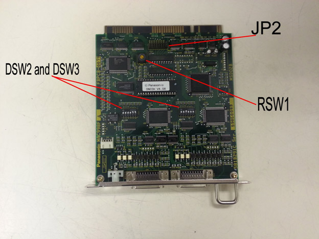
Disco’s 300 and 600 series saws have interchangeable motor control cards, all that is needed in order for these cards to work is the proper DIP switch settings. These settings are universal among machine models. In other words, an X/Y board for a DAD321 will have the same settings as for a DFD651. The relevant board part numbers are FBPCB-0076 and FBPCB-0381, if you have another version of board (this is very rare) please contact GTS for help.
Identifying the Boards
The first step is to identify which board is which. The motor control card is usually the only board that there is more than one of in the machine, they will have two black plastic rectangular connectors and one small white connector going to them. These white connectors are interchangeable among boards. The Z and Z2 boards will have an extra set of wires going into the board through the hole in the face plate as well, these wires go to a connector labeled “SETUP” and must be with the proper board. The connector for these extra wires is not visible with the board installed. If the boards are in the machine the standard order from left to right follows the numbers in the table below, with 1 being on the left and moving to the right with 2, 3, and 4. Keep in mind that the board order is interchangeable and that your machine may not have all of the options listed. If you refer to the technical reference manual for your saw there is a board layout drawing in the circuit diagram section. You can also identify which board is for which axis by the labels on the black connectors. Refer to the table below for the connector names and associated board.
DIP Switch Settings
1. X and Y Board
- Black connectors – MC1-1 and MC1-2
- RSW1: Set to “0”.
- DSW1: Not used.
- DSW2: 1 = OFF, 2 = OFF, 3 = OFF, 4 = OFF, 5 = ON, 6 = ON.
- DSW3: ALL OFF.
- JP2: Set to the position closest to the label “JP2” or remove the jumper from the board.
2. Z and Theta Board
- Black connectors – MC2-1 and MC2-2
- RSW1: Set to “1”.
- DSW1: Not Used.
- DSW2: 1 = OFF, 2 = OFF, 3 = ON, 4 = OFF, 5 = OFF, 6 = OFF.
- DSW3: 1 = OFF, 2 = OFF, 3 = OFF, 4 = OFF, 5 = ON, 6 = ON.
- JP2: Set to the position closest to the label “JP2” or remove the jumper from the board.
3. Spinner and Scope board
- Black connectors – MC3-1 and MC3-2
- RSW1: Set this to “2”.
- DSW1: Not Used
- DSW2: 1 = OFF, 2 = OFF, 3 = OFF, 4 = OFF, 5 = ON, 6 = ON.
- DSW3: All OFF.
- JP2: Set to the position closest to the label “JP2” or remove the jumper from the board.
4. Small Y and Z2 Board
- Black Connectors – MC4-1 and MC4-2
- RSW1: Set this to “3”.
- DSW1: Not Used.
- DSW2: All OFF.
- DSW3: All OFF.
- JP2: Set to the position closest to the label “JP2” or remove the jumper from the board.
Disco 300/600 Series Saw Will Not Boot/Initialize Properly
Common issues our customers have involve boot-up or initialization errors. There are three boards in the card cage that are the most likely suspects:
- Motor control board (there are at least two of these)
- CPU board
- EMSURAM Board
The 3 boards cause similar issues in that they prevent the machine from starting in some way. If you see that the machine starts up and has no splash screen (the Disco logo), the EMSURAM or the CPU are the most likely suspects. If you see a Disco logo, but the saw seems to freeze on it for an extended period of time or indefinitely, then the Motor Control Cards are the most likely cause.
Motor Control Card
Of the three different types of boards that we had listed as the likely suspects, the motor control boards tend to be the most common failure. The symptoms typically are that the saw is extremely slow to boot (often between 5-10 minutes) or does not boot at all, and then once it does finally boot, it will not initialize properly… typically an X,Y,Z or THETA CW or CCW error.
If this is the case, we then have to determine which (but it may be both) board is the culprit by following the procedure below:
With the saw booted, but not initialized go into your ENGINEERING MAINTENANCE menu, then select the AXIS MOVE screen. From this screen you will be able to initialize and manipulate each axis manually using the “F” keys as listed on the bottom of the screen. Use the arrow keys to move the cursor to the center of the screen so that it is highlighting the axis label (X, Y, Z or THETA) press the F1 key to switch between each axis, and use the F6 key to initialize each axis independently. Most likely, one or more of the axis will fault out during this procedure, and we will know which motor control board to focus on.
As mentioned above, there are two motor control boards in the card cage. They are the two identical boards sitting side by side towards the right hand side of the card cage. The one on the left will have two black connectors plugged into it labeled MC1-1 and MC1-2. This board controls the X and the Y axis. The board on the right will have two black connectors plugged into it labeled MC2-1 and MC2-2. This board controls the Z and the THETA axis. Although these two boards are 100% identical and interchangeable, there are a series of rotary switches and dip switches on them to allow the CPU to address them accordingly. At this stage, we would remove the power to the saw, remove the two boards, document the settings of these switches, then make MC1 look like MC2 and vice versa, then reinstall boards and remake all connections. Power up the saw and allow it to boot, then go back into the AXIS MOVE screen and once again initialize each axis independently. The error should have followed the board and we would know which one to replace. If all of the axis initialize properly in this screen, exit back to your main menu, and press the SYS INIT button on the keyboard. If the saw initializes properly, chances are good that the connections to the boards were loose, dirty, or otherwise compromised.
CPU and EMSURAM Boards
The CPU and the EMSURAM boards have very similar symptoms when they start to go south. When the saw is powered up and is supposed to be going through its boot sequence, there will be no display (not even the DISCO splash screen) and the saw will just sit, and sit, and sit, and eventually do nothing! If you find that one or both of these boards need to be replaced, please contact GTS for further assistance.
Both of these boards have batteries soldered to them to retain memory while the saw is powered down. When these batteries start to go bad (on either board) the saw will not boot. The CPU board is the board on the far left-hand side of the card cage. It can be identified by a red reset button near the top, and the keyboard cable plugged in near the bottom. With the saw powered OFF, remove this board and measure the voltage across the battery. It should be at 3.6 volts, If the battery measures out fine, wait about an hour with the board out of the machine and check again to see if the voltage drops. If the battery voltage is not good, the CPU is in need of repair. Please contact GTS for assistance.
The same is true with the EMSURAM board. This board is typically 2-3 boards away from the CPU and can be identified by a large, silver connector at the top, and 3 plastic connectors near the bottom. With the machine powered down, remove this board and check the voltage across the battery immediately and after one hour. It too should be 3.6 volts. Unfortunately, if the EMSURAM has a bad battery, it is not just a plug and play swap. After it is repaired, it must be formatted to operate the saw. This hard-boot requires a password that is not available to anyone other than GTS or Disco personnel. If there is an issue with this board, please contact GTS for the repair and reset.
CPU Clock Reset
In the event that both of these batteries measure out at 3.6 volts, there is one last thing you can try before contacting GTS. The CPU has a clock that can go bad and requires a reset. To do this remove the board from the machine with the power off and look at the part number on the back. If it is BPN-4D8-166, then you will need special software to continue. Please contact GTS for further assistance. If the part number does not match the one above, turn the board to the front and look for a DIP switch bank labeled SW2, usually near the battery. Note the configuration of the switches, then reverse the configuration. Install the board in the machine and turn the machine on. Wait one minute, during this time you may hear some beeps from the machine or you may see the machine boot up. Do not operate the machine at this time. After one minute turn the machine off and return SW2 back to its original order and reinstall the board. Turn the machine on, if it boots you should be good to go, if not please contact GTS for further help.
Procedure for Installing and Re-teaching the Height Button on a K&S 780 or 980 Dicing Saw
Start up the dicing saw and perform a height check as normal.
Access the Stations Teach screen by pressing Shift+Stop keys, then press the Teach key until the Teach screen is displayed.
Select “Stations” then press 8 for “Button”.
Remove old button, insert the new one, then level as pictured below using the K&S levelling tool. Apply pressure with your hand over the chuck table to ensure the button is equally level with the chuck.
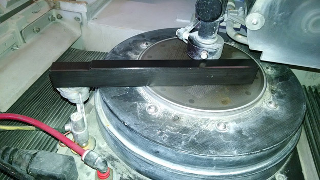
Once the collar for the button is tightened, remove the levelling bar and store for future use.
Once completed, press "D" for Teach.
The saw will then ask you to verify that the spindle and camera stations have been accurately taught, just press "Enter" to continue.
Now a screen will pop up asking what your desired level of parallelism, and desired effective button diameter are to be. Enter data accordingly, press Enter to continue.
Saw will then prompt you to perform a chuck table set up. Be sure to move the chuck as necessary to ensure that the blade makes contact with the flat, metallic surface, and not a groove or the ceramic portion of a porous chuck table.
* The next instruction will be different between the K&S 780 and the K&S 980 dicing saw. The K&S 780 will begin to descend from its Z upper limit, whereas the K&S 980 will allow you to scan the Z axis down to its lower soft limit before descending on its own. *
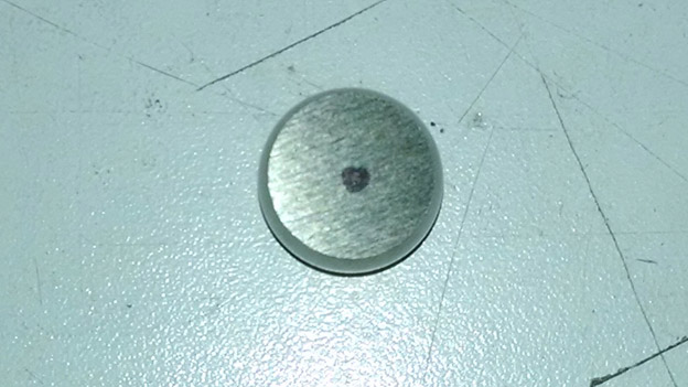
Press Enter, and the blade will descend to make contact with the chuck table. Once it finishes, it will ask you to make sure that you are in button focus. Scan so that the camera is looking at the center of the height button. I will use a Sharpie and mark a small dot near the center of the button so that I can easily find this center with the camera (see image below).
Press Enter, and the saw will prompt you to verify contact locations by moving the camera to 4 locations on the surface of the button. These positions are determined by the effective diameter programmed in the earlier screen.
Once all 4 locations are verified, press Shift + Enter and the saw will automatically contact on all four locations to verify the parallelism programmed in the earlier screen has not been exceeded.
Once it is completed and the parallelism has been verified, press Shift + Enter to save the data.
Exit to Main Menu.
End.
K&S 780-980 Saws Chuck Open Error
There can be many different reasons that you might get a chuck open error on your dicing tool. Here are a couple of things that you may want to look at to try and solve the problem.
There are 3 possible things that can give you this error on the K&S tools.
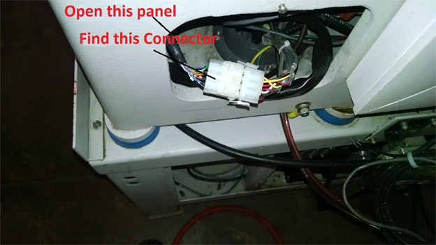
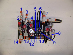
1. Check for wire damage between the B connector that is under the air take in the back right hand corner of the machine behind the black plate. You will need to Ohm the wires from this connector to the two wires that are under the chuck table. What you are looking for by doing this is if you have continuity between the chuck table and the connector in the back of the machine
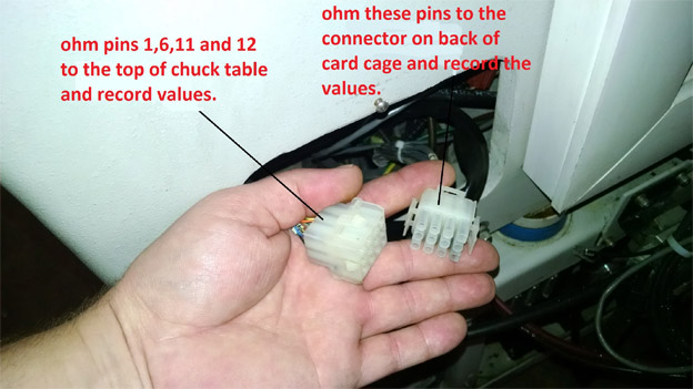
2. You are going to want to check continuity between the height button and the top of the chuck table.
3. If you have continuity in the first two checks, your next step would be to try and replace the Main logic board.
If you still have a problem, give us a call.
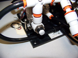
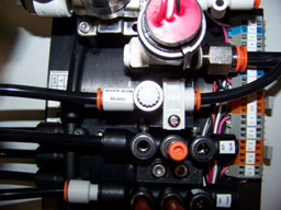
Information about the GTS Utilities Block
This will provide you with information related to the utilities block designed as a replacement for the 780 and 980 dicing saws. If you have any further questions please contact GTS by phone or email.
Air, Water, and Vacuum Connections
- Cutting Water
- Water Gun
- Vacuum Input
- Spindle Water In
- Air Gauge
- X
- Main Air
- Scope Blow
- Y
- Air Gun
- Air Tank
- Spindle Water Out
- Vacuum Out
- Cutting Water Out
Sensors and Adjustments

- Cutting Water Sensor
- Chuck Blow Off
- Vacuum Sensor
- Spindle Water Sensor
- Scope Blow Off (Inspection)
- Scope Blow Off (Always On)
- Main Air Sensor
The four sensors are preset to safe levels but may need to be adjusted depending on your needs. The default values are: 15 mmHg for vacuum, 40 psi for both waters, and 60 psi for air. The three throttle valves are not set and need to be adjusted for your process. There are no spec numbers for these so you may need to experiment to get the right settings.
Chuck Blow Off
Scope Blow (Always On)
Scope Blow (Inspection)
Checking Run Out on a Wheel Mount or Flange
Tools Needed:
- Indicator stand with adjustable arm and magnetic base
- Magnetic dressing jig or other magnetic plate
- Micron dial gauge
- Universal or maintenance chuck table
Procedure:
- Remove the blade from the wheel mount or flange.
- Move the Y axis to the rear limit of the machine.
- Place a magnetic jig in the middle of the chuck table. You must use a universal or maintenance chuck table that is capable of pulling vacuum on the jig. Most dressing jigs are magnetic, but any magnetic plate will work as long as the machine can pull vacuum on it.
- Turn the vacuum on.
- Mount your indicator stand with dial gauge attached to the jig.
- Adjust the stand and gauge so the needle of the gauge can touch the mating surface of the wheel mount or flange. Be sure that the needle runs parallel to the direction of rotation. See “Dial Gauge Setup” diagram for more detail.
- The needle should touch a point on the mating surface that will come in contact with the blade (in the case of flanges) or hub/flange (in the case of wheel mounts). This point is the outer edge for flanges and the center for wheel mounts. See the “Mating Surface” Diagram for more detail. Be sure that the needle can deflect in both directions when touching the mating surface.
- Rotate the nose of the spindle slowly by hand, being careful not to disturb the dial gauge or indicator stand. It may help to spin the nose and let go so it rotates freely, just note that the initial force may cause some deflection in the needle. You will need to compensate for this by ignoring the first spike on the gauge.
- After several rotations, note the deflection of the gauge.
- Dress the wheel mount or flange if needed by referring to the appropriate dressing procedure, “How to Manually Dress a Wheel Mount” or “How to Manually Dress a Flange”.
Dial Gauge Setup
Mating Surface
How to Manually Dress a Flange
Tools Needed:
- Dressing jig
- Dressing stone
- Universal or maintenance chuck table
Note: This procedure is for older saws that are not equipped with a built in dress function in the software. Most of the newer saws have an automatic function for this.
Procedure:
- Remove the blade.
- Check the run out of the flange with a dial gauge, refer to “Checking Run Out on a Wheel Mount or Flange” for instructions. The flange should have less than .001µm of run out.
- Move the Y axis back to its rear limit.
- Place the dressing jig on the chuck towards the rear of the machine, do not place it under the spindle where the Z might crash into it when lowered. You must use a universal or maintenance chuck capable of holding vacuum on the jig.
- Move the Z axis down to where the stone on the jig and the mating surface of the flange are on the same level when the stone is directly underneath the spindle nose.
- Move the Y axis forward until the mating surface and the stone meet, continue moving the Y axis forward pushing the dressing jig until it reaches the center of the chuck. This aligns the stone to the mating surface and places the jig where the vacuum can hold it in place.
- Now move the Z axis down so that the stone no longer makes contact with the mating surface. Be sure that the jig is not touching the nose of the spindle or any other part of the flange and the stone is not touching the sleeve!
- Turn the chuck vacuum on and ensure there is good suction.
- Adjust the spindle RPM to 10000-15000 RPM.
- Once the spindle is up to speed, move the X axis from right to left across the mating surface. Then move it from left to right returning it to its original position underneath the spindle nose. Repeat this 2 (for taking off more material) or 4 (for polishing) times. This is 1 cycle, which should end with the stone underneath the nose of the spindle.
- Now use the Y index set to .005µm (for taking off more material) or .003µm (for polishing) and move the Y forward 1 index.
- Repeat a complete cycle as described in step 10. Keep in mind that you may or may not see sparks or hear grinding initially, but it will start to happen.
- Continue repeating cycles, stopping to check the flange every 10-20 cycles with a dial gauge. Once the flange is in spec (.001µm or less for most flanges), use the polish numbers mentioned above to finish off the process if you weren’t already using those settings. Do this for 5-10 cycles.
Front View of Flange
Side View of Flange and Jig
Top View of Jig

How to Manually Dress a Wheel Mount
Tools Needed:
- Dressing jig
- Dressing stone
- Universal or maintenance chuck table
Note: This procedure is for older saws that are not equipped with a built in dress function in the software. Most of the newer saws have an automatic function for this.
Procedure:
- Remove the blade and/or flange.
- Check the run out of the wheel mount with a dial gauge, refer to “Checking Run Out on a Wheel Mount or Flange” for instructions. The wheel mount should have less than .002µm of run out.
- Move the Y axis back to its rear limit.
- Place the dressing jig on the chuck towards the rear of the machine, do not place it under the spindle where the Z might crash into it when lowered. You must use a universal or maintenance chuck capable of holding vacuum on the jig.
- Move the Z axis down to where the stone on the jig and the mating surface of the wheel mount are on the same level when the stone is directly underneath the spindle nose.
- Move the Y axis forward until the mating surface and the stone meet, continue moving the Y axis forward pushing the dressing jig until it reaches the center of the chuck. This aligns the stone to the mating surface and places the jig where the vacuum can hold it in place.
- Now move the Z axis down so that the stone no longer makes contact with the mating surface. Be sure that the jig is not touching the nose of the spindle or any other part of the wheel mount!
- Turn the chuck vacuum on and ensure there is good suction.
- Adjust the spindle RPM to 10000-15000 RPM.
- Once the spindle is up to speed, move the X axis from right to left across the mating surface. Then move it from left to right returning it to its original position underneath the spindle nose. Repeat this 3 (for taking off more material) or 5 (for polishing) times. This is 1 cycle, which should end on the opposite side of the mating surface from which it started.
- Now use the Y index set to .005µm (for taking off more material) or .003µm (for polishing) and move the Y forward 1 index.
- Repeat a complete cycle as described in step 10. Keep in mind that you may or may not see sparks or hear grinding initially, but it will start to happen.
- Continue repeating cycles, stopping to check the wheel mount every 10-20 cycles with a dial gauge. Once the wheel mount is in spec (.002µm or less for most wheel mounts), use the polish numbers mentioned above to finish off the process if you weren’t already using those settings. Do this for 5-10 cycles.
Front View of Wheel Mount
Side View of Wheel Mount and Jig
Top View of Jig